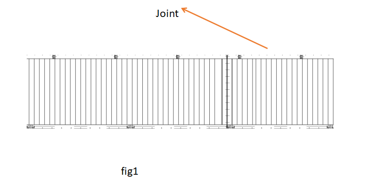
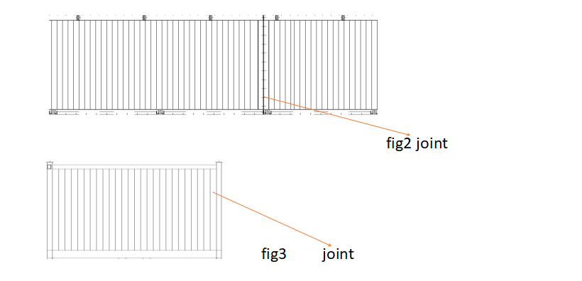
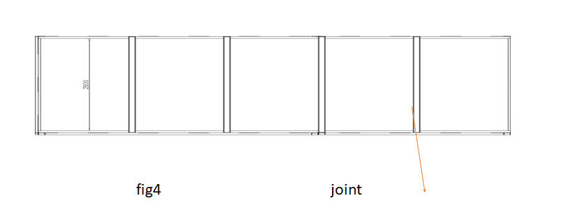
1:On the horizontal area, the two long silo body plates of the cement silo are connected with bolts, and the joint is evenly coated with sealant.
2:Connect the four cement silos bodies with bolts according to the number (1-1, 2-2, 3-3, 4-4), and apply sealant evenly at the connection.
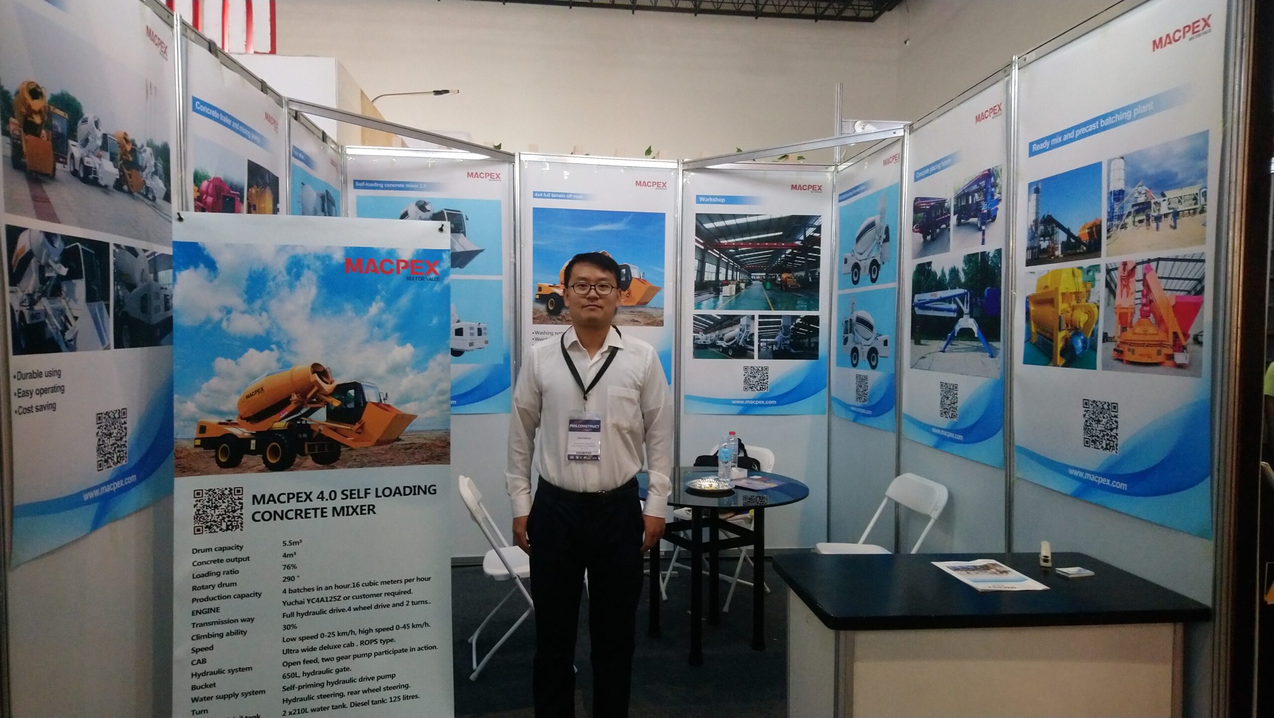
3:Install the bottom cross brace and the top cross brace of the cement silo. The bottom of Fig4 is 14 channel steel, installed in the order of 1-1, 2-6, 3-7, 4-8. The top is 10 channel steel, which is installed in the order of a, B, C, D, e, F and G.
4:Install the ash inlet pipe of cement silo in sequence. Flange comparison, flange with gasket in the middle, bolt tightening.
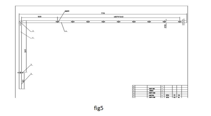
5:Install the cone of cement silo. Before installing the cone, install the flow aid inside the cone (Fig6), 3 cones for each cone, wrapped with raw tape and installed (Fig7).
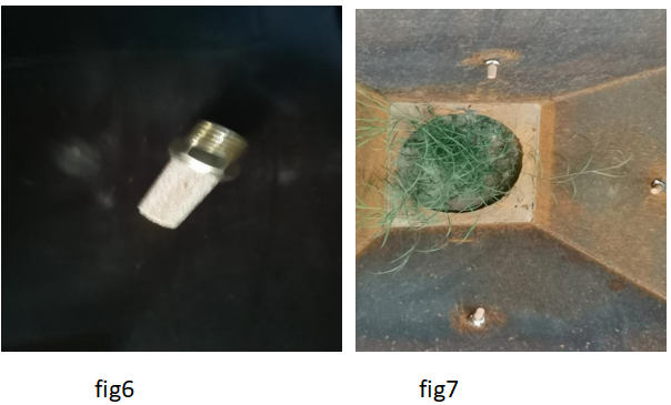
Put the bottom of the cement silo body upward, and then install each cone (fig8) according to the labeling sequence. Apply the sealant evenly.
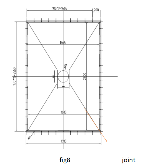
6:Install the guardrail under the cement silo, and install 4 pieces in total according to the labeling sequence. Apply the sealant evenly.
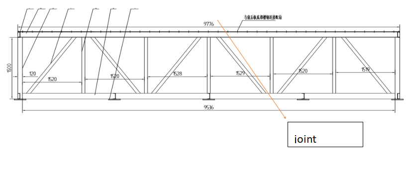
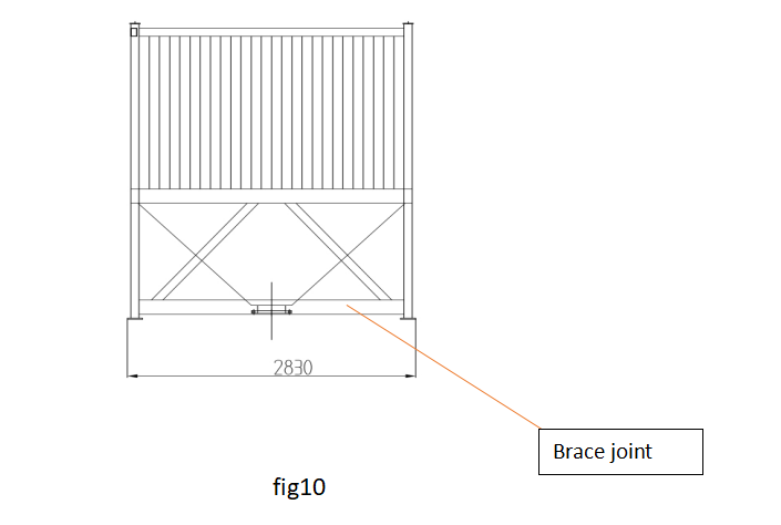
7: Install the cross brace of guardrail (Fig10) according to the label of cross brace (2-2, 3-3, 4-4).
8:Turn over the installed cement silo, make its top up, start to install the top cover, and install it according to the serial number. Apply the sealant evenly. Note: sealant must be applied to all joints. After installation, the top plates are welded with welding machine, and the welding is firm.
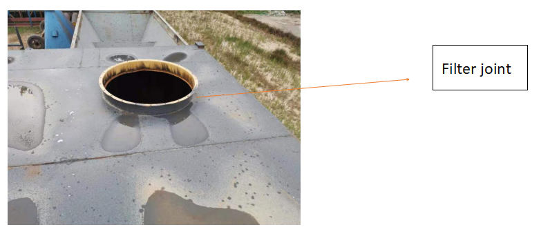
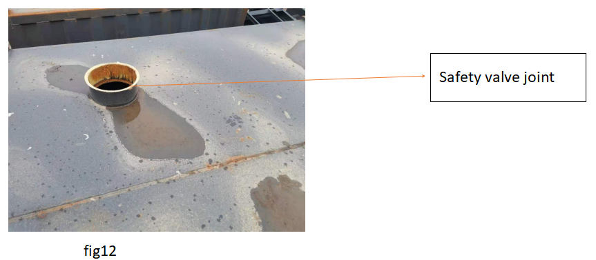
9: Install the dust remover on the top of cement (Fig11), and connect the dust remover with the base with bolts. The safety valve (Fig12) uses the hexagon tool to open the clamp, then uses the clamp to clamp the safety valve and the safety valve base, and uses the hexagon tool to tighten the bolt.
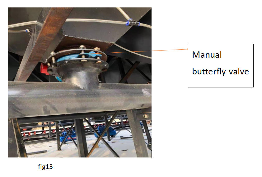
10:For the installation of horizontal screw machine, first check the screw inner core, connect the letter inner core well, and do not fall off. Then the flange bolt holes are compared, and the leather gasket is added in the middle, and the flange is firmly connected with bolts. Then install the motor, the motor shaft is connected with the inner sleeve of the reducer, and the shaft and the sleeve are stuck with keys. Lift the cement silo to make its discharge port correspond to the feeding port of screw conveyor, install manual butterfly valve (Fig13) in the middle, and then connect it firmly with bolts.
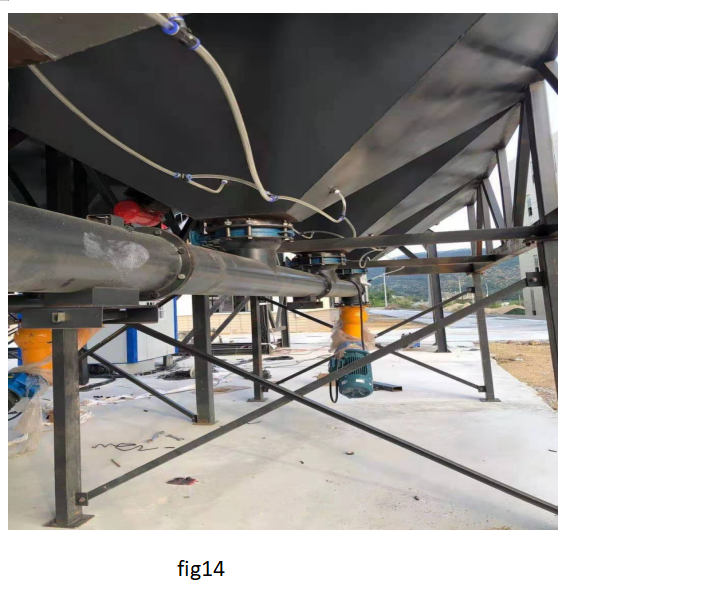
11:Install cement silo outrigger and outrigger diagonal brace (Fig14). Lift the whole cement silo, connect the flange of outrigger with the flange of cement silo with bolts, do not tighten the bolts, and install diagonal braces between outriggers. After all the bolts are connected, screw them firmly with spanner.
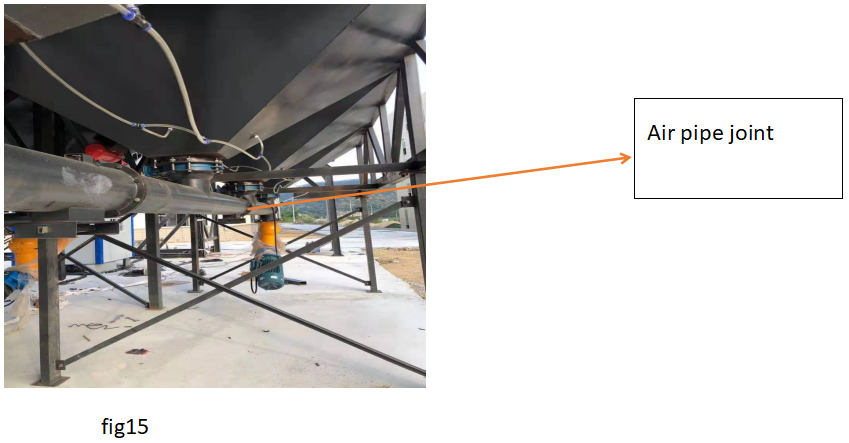
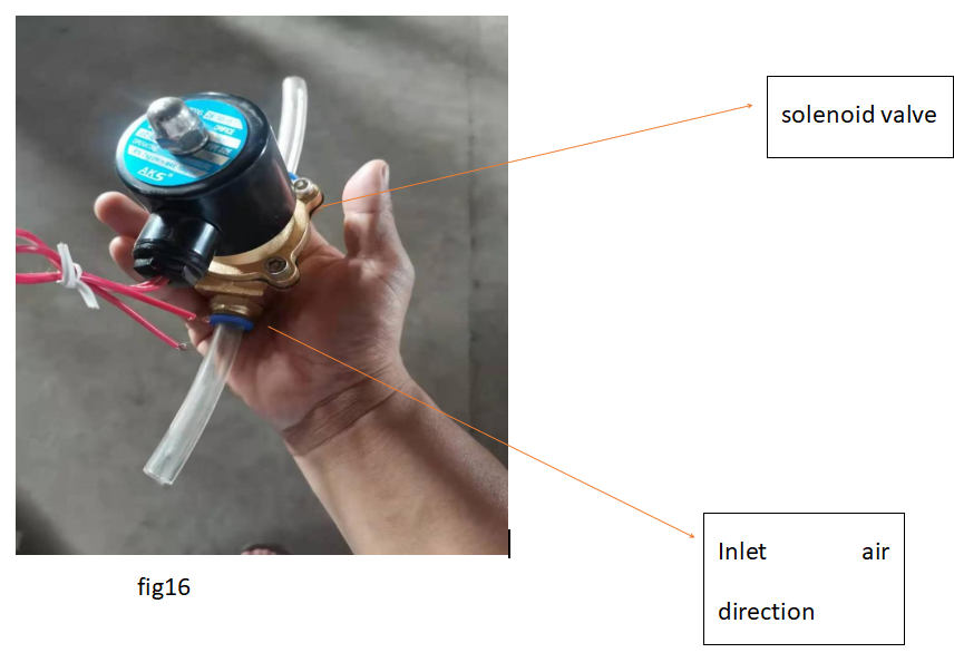
12: To install the air pipe (Fig15), first wind the air pipe joint (3 for each cone) with green tape and install it. Then connect each of them with a gas pipe, leave the inlet end connected with the outlet end of the solenoid valve (Fig16), and the inlet end of the solenoid valve connected with the air compressor.
13: Install the vibrator of each cone and connect it firmly with bolts.

